+86-18080970736



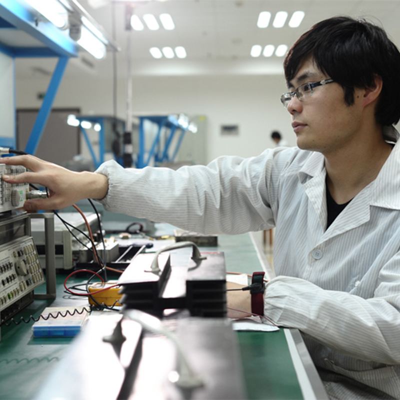

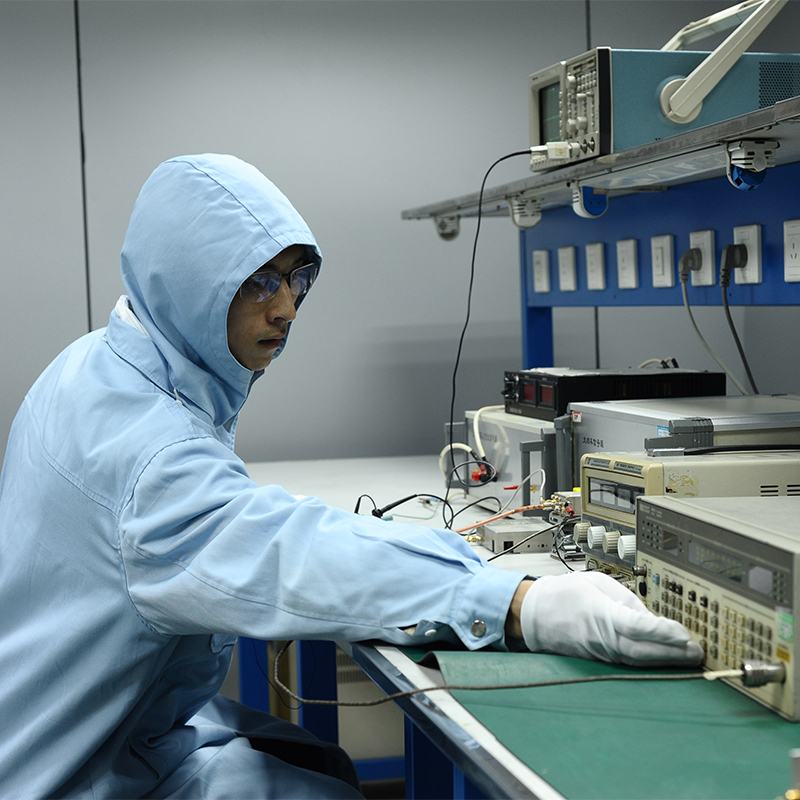




Switching time measurement system
Product description The system is designed to measure time parameters such as switching time. In some scenarios, a zero-scan spectrum analyzer may be temporarily used as an oscilloscope. Structural scheme for measuring switching time Figure 5.
Description
marker
Product description
The system is designed to measure time parameters such as switching time. In some scenarios, a zero-scan spectrum analyzer may be temporarily used as an oscilloscope.
Structural scheme for measuring switching time

Fig. 5. Structure diagram of the switching time measurement system
Key points during measurements
When building a measuring system, all components must be reliably connected to a dedicated grounding line. It is strictly forbidden to use the power grid neutral as a protective grounding for the measuring system.
It is necessary to follow the established procedures and operating rules of the oscilloscope when switching on, calibrating, measuring and turning off.
The measurement conditions shall comply with the requirements.
The values of pulse delay, front length and recession duration shall be determined in accordance with generally accepted definitions.
contact us
Send an inquiry
Related popular products
detector
Review of the product The detector is a specialized device that converts high frequency.
power amplifier
Review of the product Power amplifier is a key active device in radio frequency.
Receiving channel module
Review of the product Any radio device that has a reception function must have a...

System of vector analysis of chains
Review of the product A vector chain analyzer is a specialized measuring appendage.
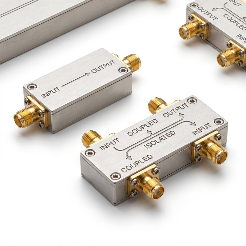
directional coupler
Review of the product directional coupler is a specialized device for selecting...
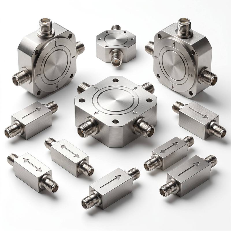
Circulator, isolator
Review of the product Circulator and isolator are specialized control devices on the...
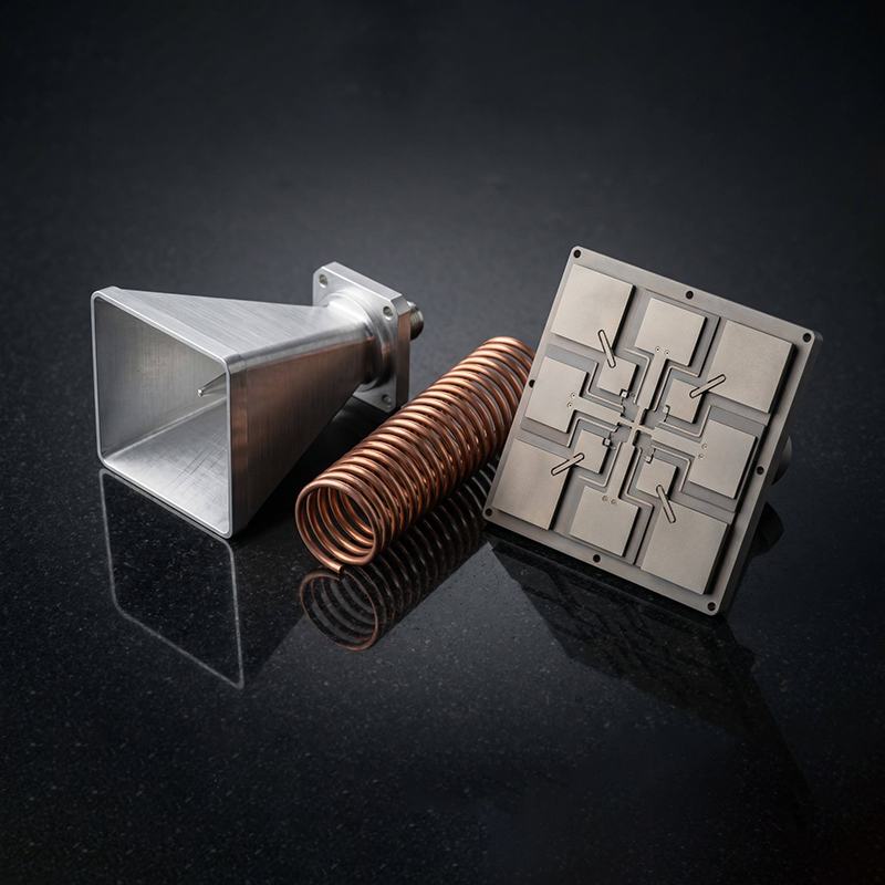
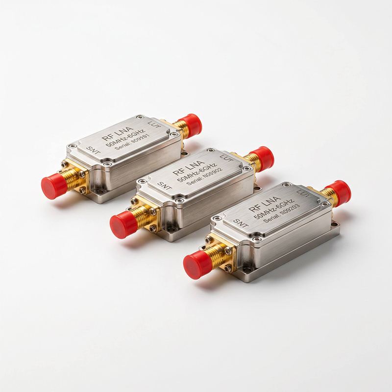
low-noise amplifier
Review of the product The low-noise amplifier is mainly used in the input cascades.

System for measuring spectral characteristics and power
Structural scheme of the measuring system The measurement system is divided into a system...
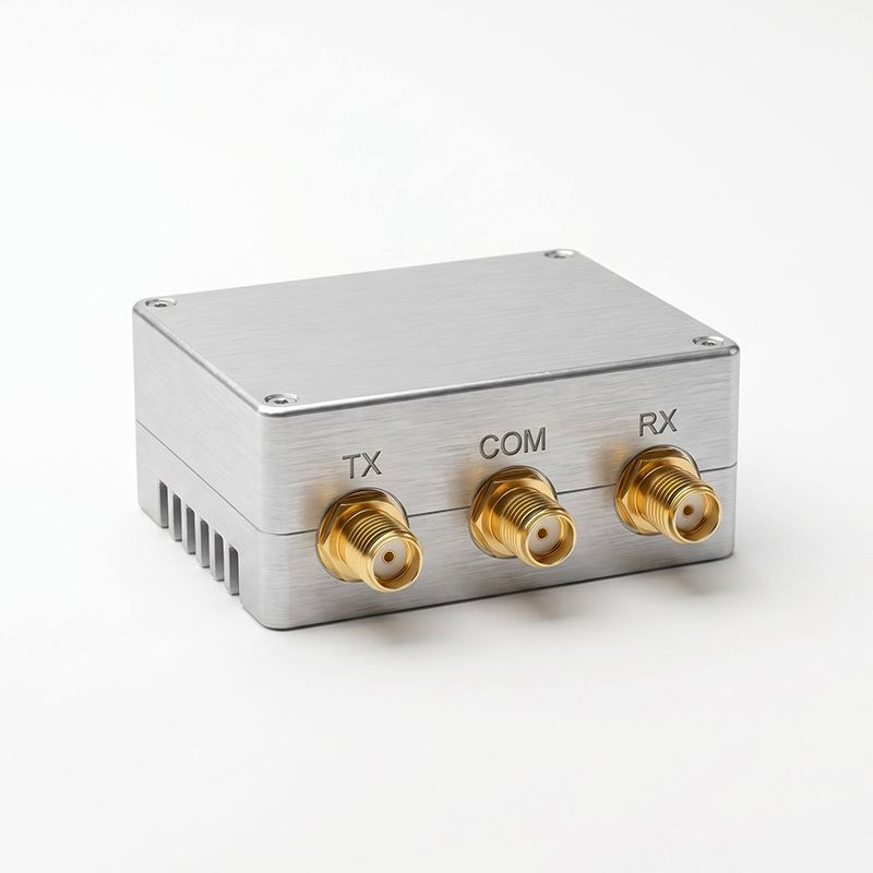
Transmission switch module
Review of the product In systems with time separation of reception and transmission, such as radio
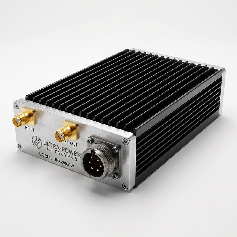
Power amplifier module
Review of the product A device that amplifies the signal level of a frequency source or input
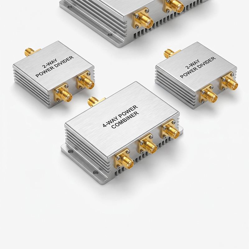
power divider/combiner
Review of the product The power divider/summator divides a single signal into ...
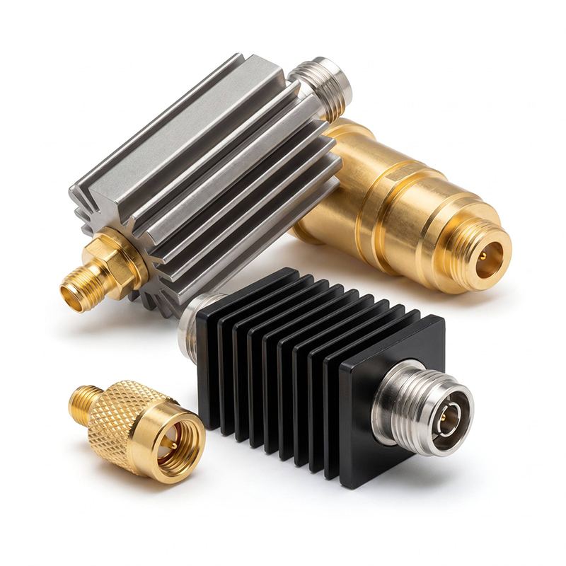
matched load
Review of the product The agreed load is a specialized terminal device d...
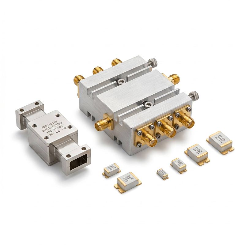
Filter
Review of the product The filter is a key device for frequency selection, suppression of pa...
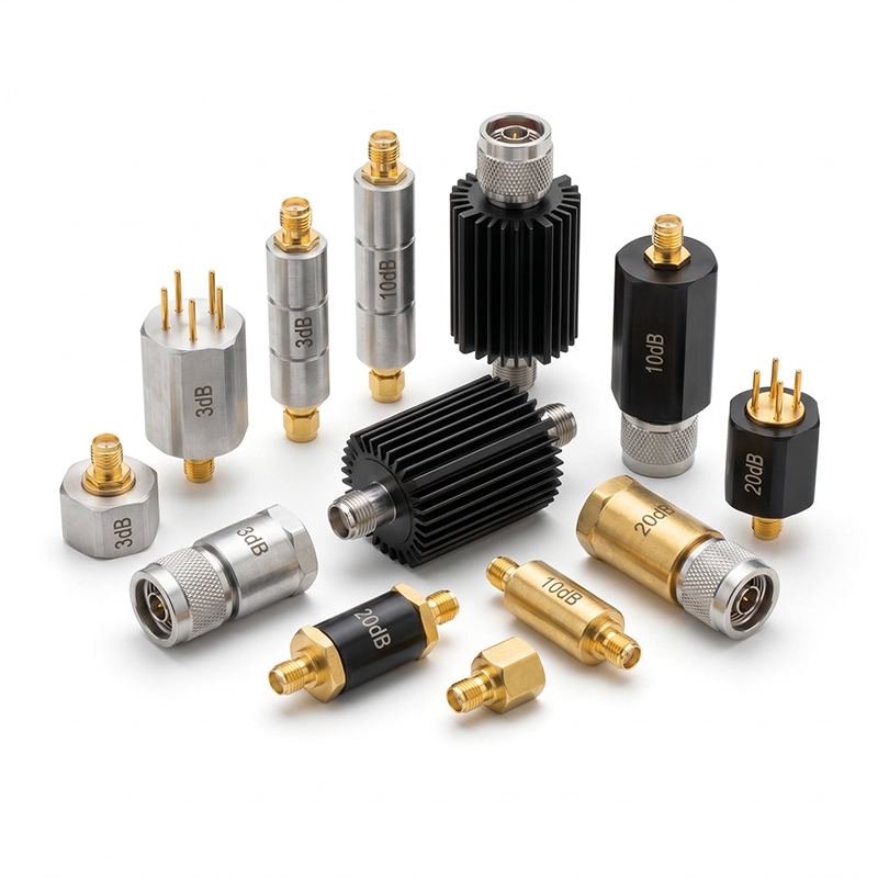
attenuator
Review of the product Attenuators are divided into fixed and regulated. They're predestined...