
+86-18080970736









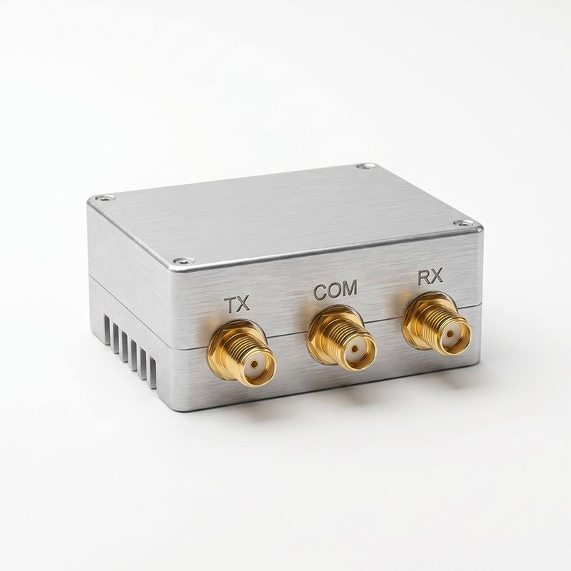
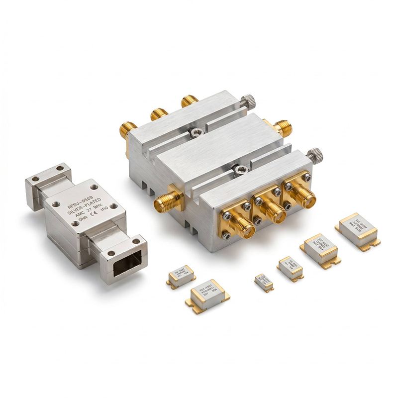

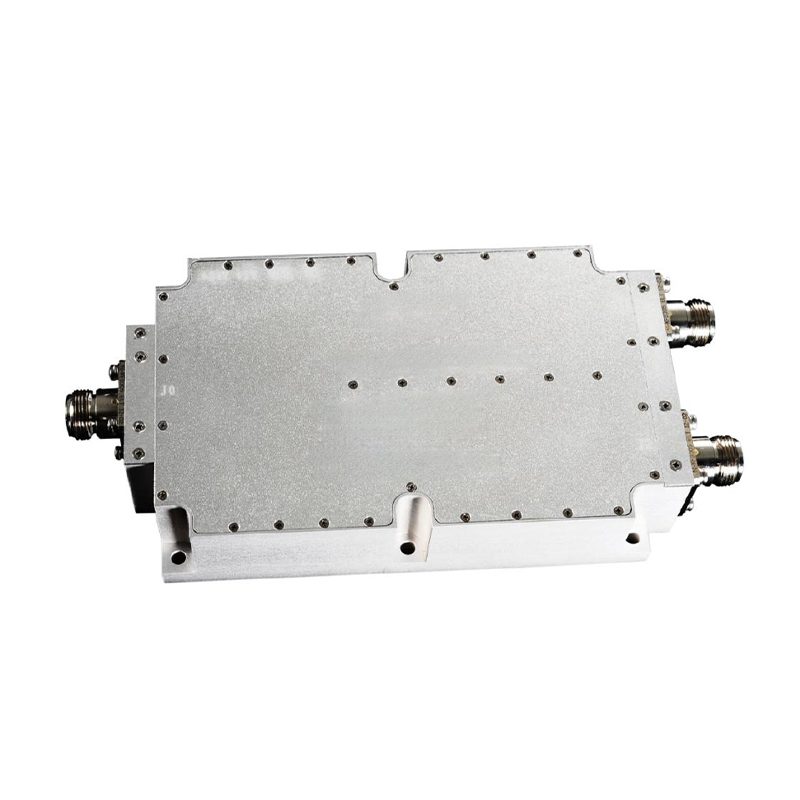
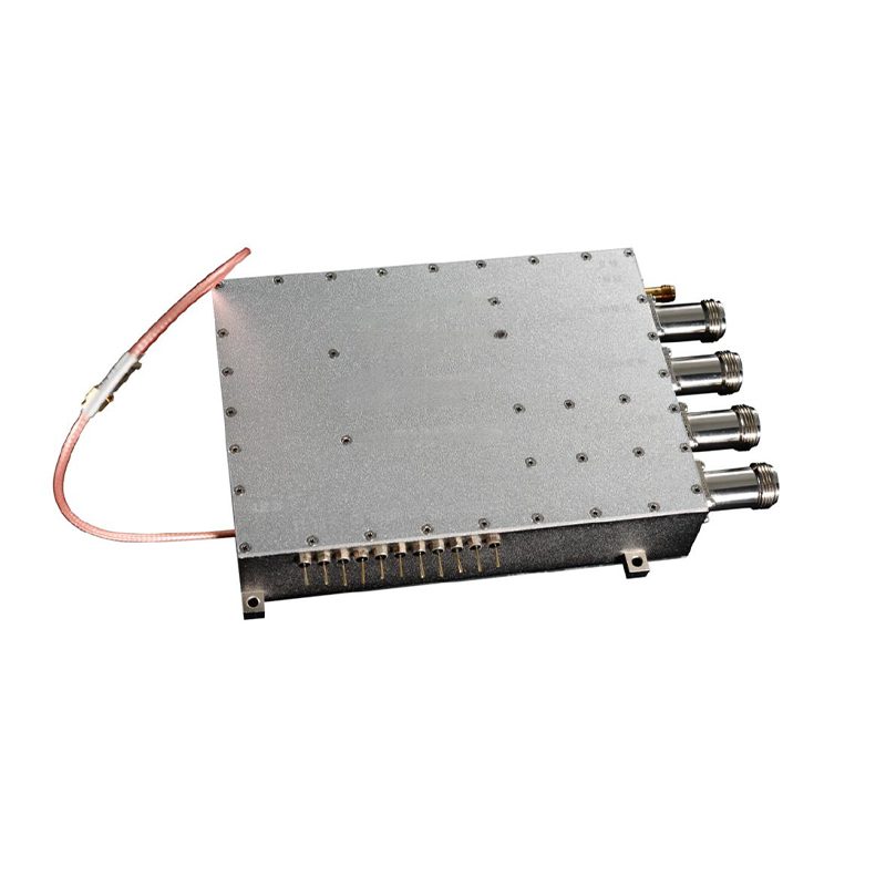
Transmission switch module
Review of the product In systems with a time division of reception and transmission, such as radar stations, radio stations and sonar, a single-pole switch in two directions is used, which alternately connects the common antenna to the transmitter and receiver, providing alternate ...
Description
marker
Review of the product
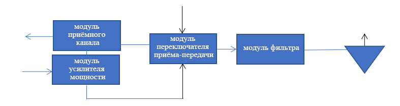
In systems with time separation of reception and transmission, such as radar stations, radio stations and sonar, a single-pole switch in two directions is used, which alternately connects the common antenna to the transmitter and receiver, providing alternate transmission and reception. Such a switch that performs the function of single-pole switching in two directions is called a receive-transfer switch. The key indicators of the receive-transmission switch are the permissible power, the switching speed, the losses in the on state and the isolation in the off state. To control spectral characteristics, a filter is often installed on the antenna port. A block diagram of the connection of circuits before and after the receive-transfer switch is shown in the figure.
Key functions
• Managed switching between receiving and transmitting modes to provide alternate transmission and receiving with time separation.
• Connecting a filter to implement frequency-selective reception and transmission, as well as to suppress interference and noise.
Scope of application
It is used in systems with time separation of reception and transmission, such as radar stations, radio stations, etc.
Typical technical parameters
| Name of the parameter | Operating frequency range | Permissible power | Loss incurred | Switching speed | harbour security | Transmitted power | Operating temperature | Constructive implementation |
| Model indicators | 10 MHz ~ 100 GHz, optionally | 10 dBm ~ 63 dBm, to order | 1~3 dB, depending on frequency range and requirements | from μx units to ms units, by order or option | 1.2~2, to order | 10 MW ~ 3000 W, to order | -40 °C ~ +85 °C, to order | Module, hull execution, to order |
contact us
Send an inquiry
Related popular products

Switching time measurement system
Product description The system is designed to measure time parameters such as...
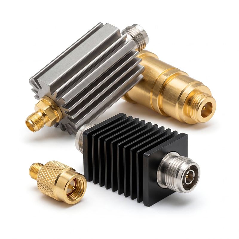
matched load
Review of the product The agreed load is a specialized terminal device d...

System for measuring spectral characteristics and power
Structural scheme of the measuring system The measurement system is divided into a system...
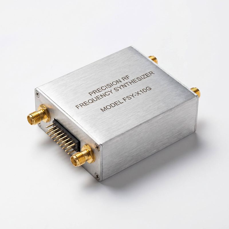
Frequency source module
Review of the product In electronic circuits, a frequency source is a device that provides...
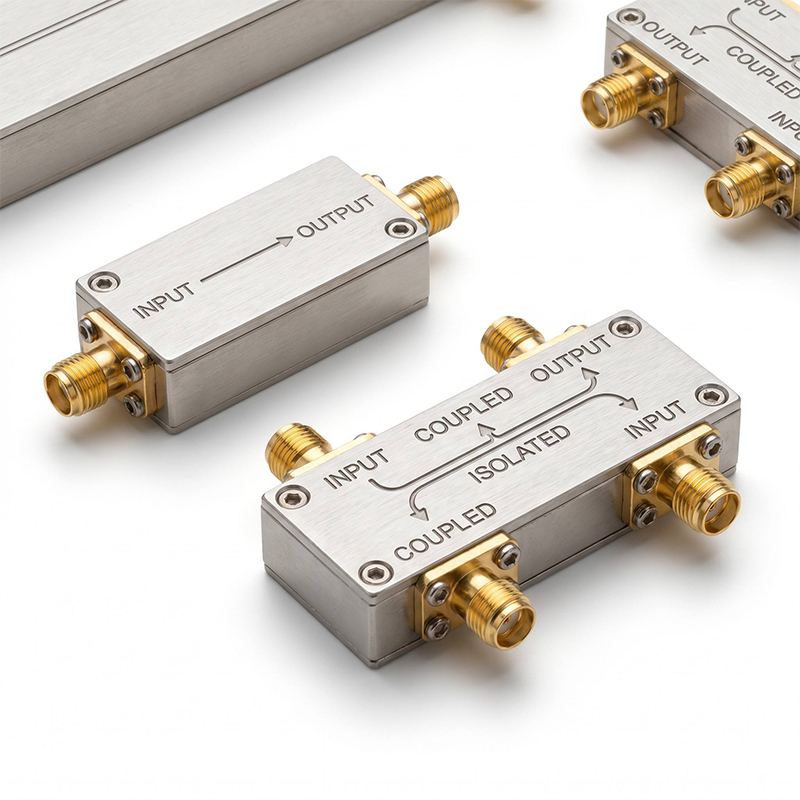
directional coupler
Review of the product directional coupler is a specialized device for selecting...
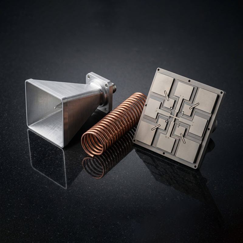
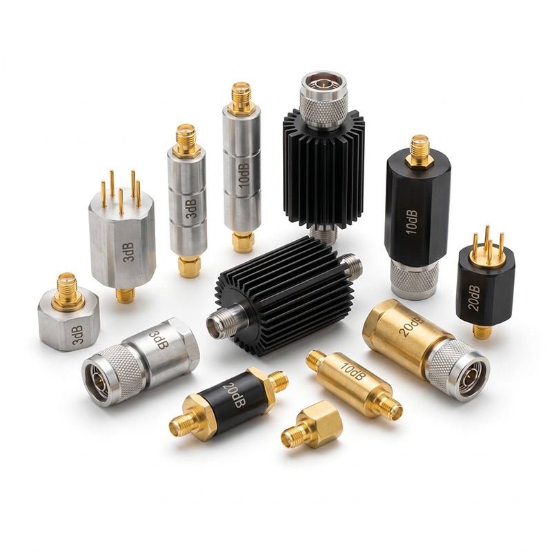
attenuator
Review of the product Attenuators are divided into fixed and regulated. They're predestined...
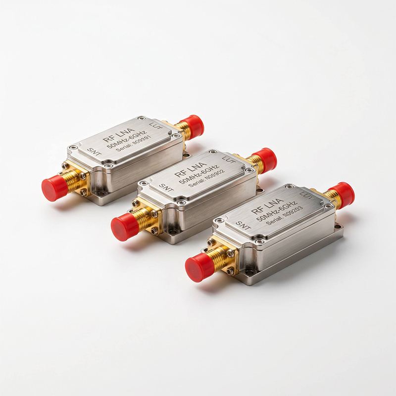
low-noise amplifier
Review of the product The low-noise amplifier is mainly used in the input cascades.
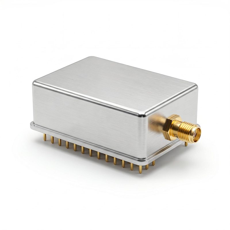
signal generator
Review of the product The generator is a device for the formation of a reference frequency in radio frequency.
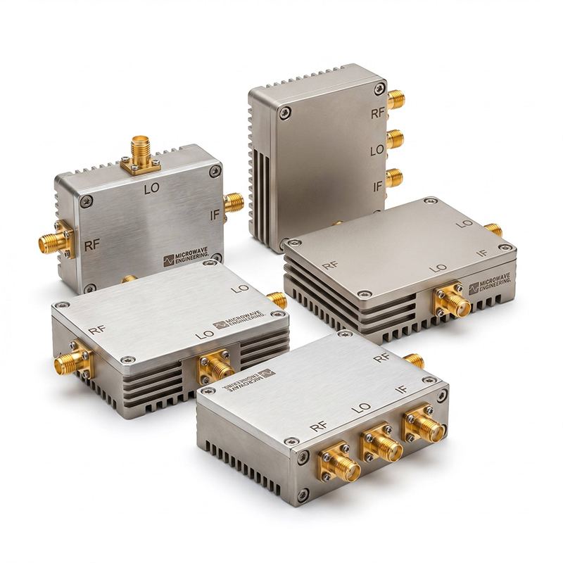
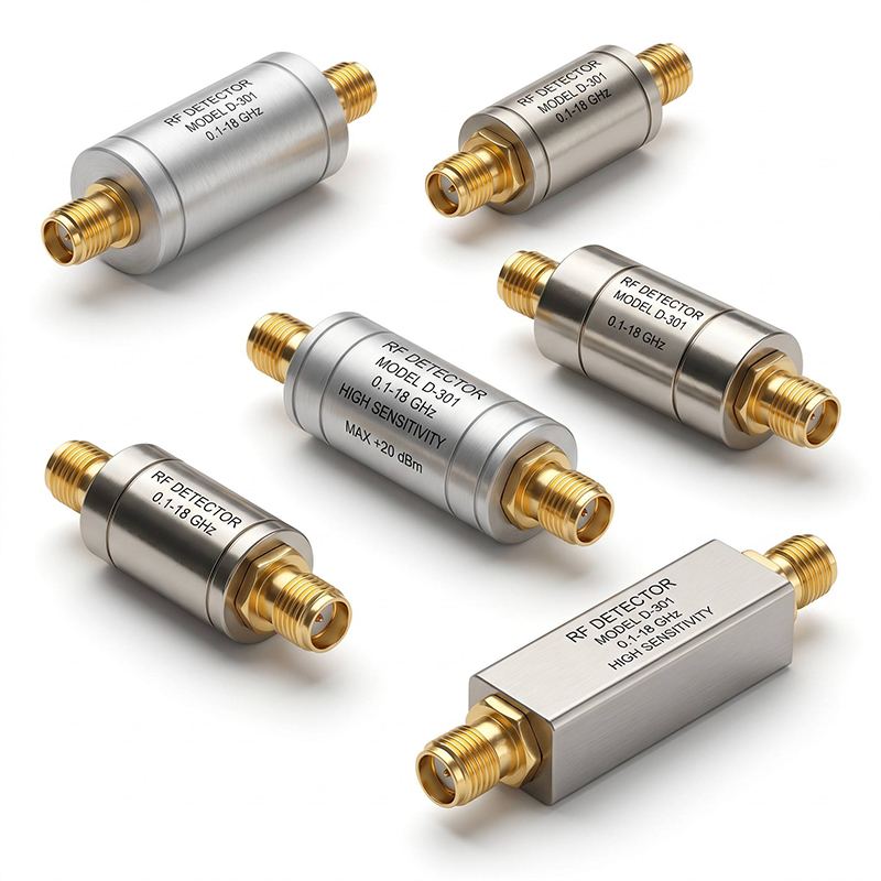
detector
Review of the product The detector is a specialized device that converts high frequency.
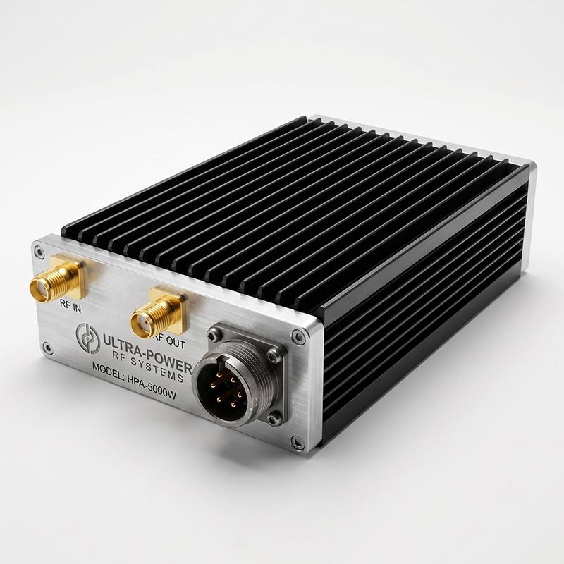
Power amplifier module
Review of the product A device that amplifies the signal level of a frequency source or input
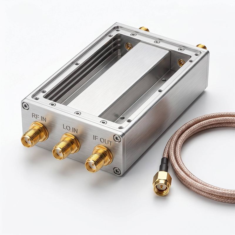
Receiving channel module
Review of the product Any radio device that has a reception function must have a...
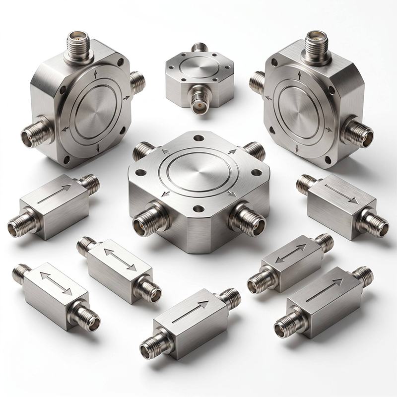
Circulator, isolator
Review of the product Circulator and isolator are specialized control devices on the...
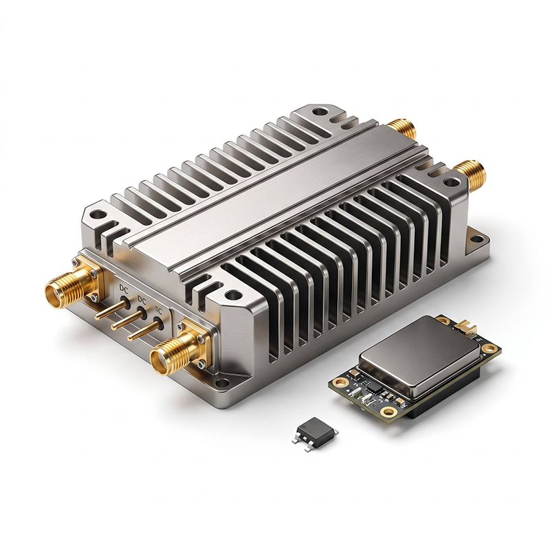
power amplifier
Review of the product Power amplifier is a key active device in radio frequency.
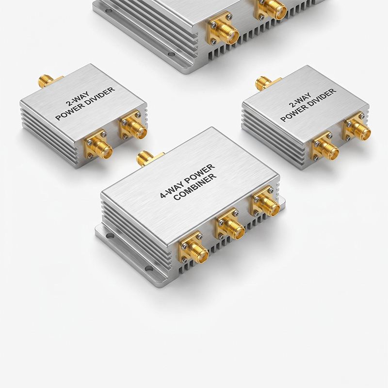
power divider/combiner
Review of the product The power divider/summator divides a single signal into ...